| CS 354 | Computer Organization and Systems | Fall 2019 | |
Opening the Gate: Exploring the Electronics at the Heart of Modern ComputersLearning Goals and Objectives
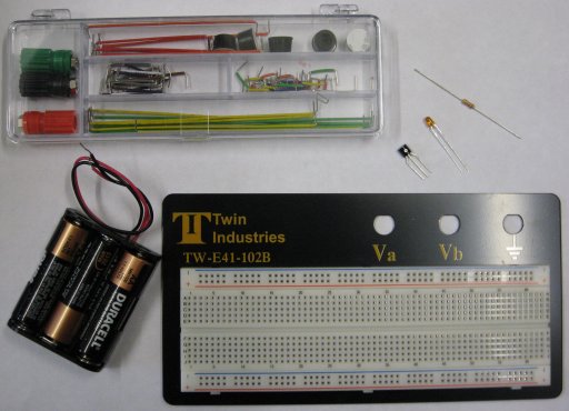
Parts List
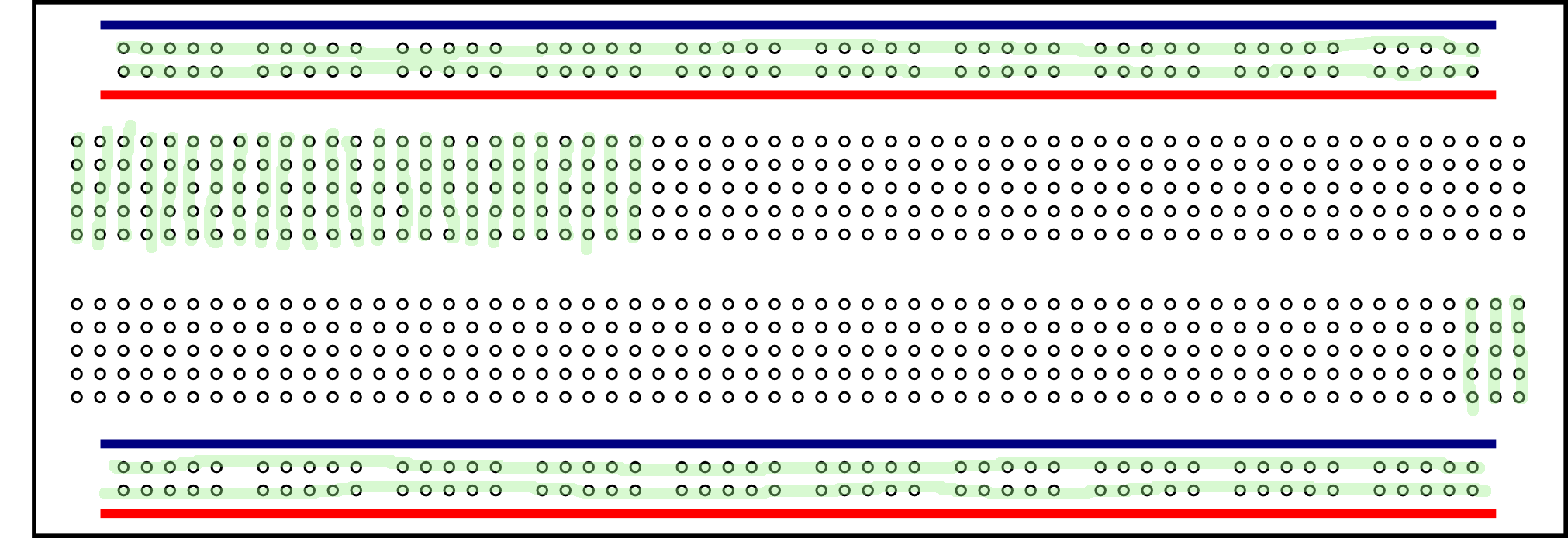
Breadboards and Wiring
Basic Circuits and Batteries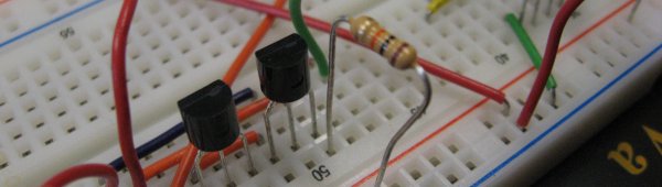 Electricity is the flow of electrons in materials from a positively charged region to a negatively charged region. Current, measured in amps (A), is the amount of electrons flowing in a circuit. Common metals used in electrical circuits such as tin, copper, gold, and tungsten easily conduct electrify and are called conductors. Materials like air, glass, and plastic do not easily conduct electricity and are called insulators. Elements such as Silicon and Germanium are called semiconductors, because they can be either insulators or conductors, depending on some external charge, temperature change, or incident light.
Voltage, measured in Volts (V), is the potential for current to flow from one part of a circuit to another. Certain electronic components restrict or break the flow of current in circuits. The voltage difference across an electronic component governs the amount of electricity that will flow through the component.
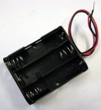
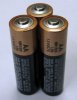
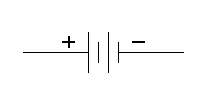
Batteries store electricity that is released through a chemical reaction. A single AA battery has a voltage of 1.5 V and can deliver an amperage of 1 A for 1-2 hours. Our battery holder connects three AA batteries in series (end-to-end) to provide a combined voltage of 4.5 V. Batteries are represented in circuit diagrams as a shown in the figure on the above right. Electrical circuits control the flow of current to perform a desired task. The flow of electricity is controlled by electronic components which comprise an electronic circuit. A path for current flow must exist between the positive and negative sides of the batteries. If no such path exists, the circuit is said to be an open circuit and no current will flow. In circuit diagrams, lines are used to represent paths connecting electronics components (as will soon be illustrated).
Diodes, LEDs, and a Simple Circuit
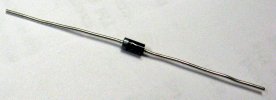
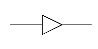
A diode is an electronic component that restricts the flow of electricity to only flow in one direction, similar to the way a one-way door, turnstile, or check-valve only allows a one-way flow. Diodes have two electrodes, typically connected to a cylindrical housing containing a semiconductor with a P region on the positive side (called the anode) and an N region on the negative side (called the cathode). See the diagrams above to see an example picture of a diode and how a typical diode is represented in electronic circuits. The cathode side is commonly labeled with a line.
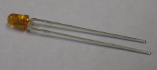
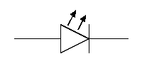
A Light Emitting Diode (LED) is a special diode that emits light, based on the observation that as an electron loses energy going from the P region to the N region in some semiconductors, a visible photon is emitted with the same energy as the energy change in the electron across the P-N junction. Rather than a cylindrically symmetric shape, LEDs typically have two parallel electrodes with the longer leg corresponding to the anode (positive) side and a flattened region on the cathode (negative) side. LEDs are fun because they bring life to electronic circuits by letting us see where there is a flow of electricity. See the diagrams above to see an example picture of a LED and how a typical LED is represented in electronic circuits. 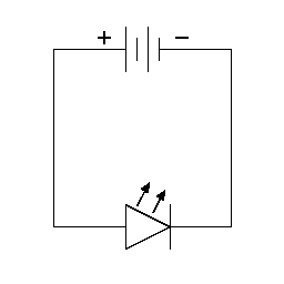
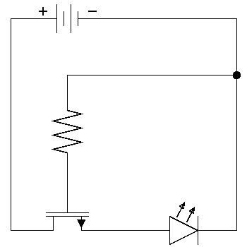
Our LEDs have a combined resistor to reduce the amount of current flowing through the device (more on resistors in a moment). Normally you would always need an additional resistor to control the current flow through the LED to control light output and to avoid damage. Build the circuit shown in the diagram on the right. The easiest way to do this is to connect the battery wires to the corresponding terminal blocks. Using jumper wires, connect the positive and negative bus lines to the terminal blocks. Simply place the LED between a positive and negative hole pair on the bus lines. Avoid spreading the electrodes of the LED too far apart (if at all). When the battery is connected, the LED should glow. Note that most of the light from the LED is emitted from the top and not much is visible from the sides. Observe that the LED will not glow if it is connected in the opposite direction. Congratulations! You have just created a simple battery tester! Note this also serves as an indicator that the circuit is "ON", so you should leave this LED in place for all of the following experiments to help troubleshoot your experiments. Resistors
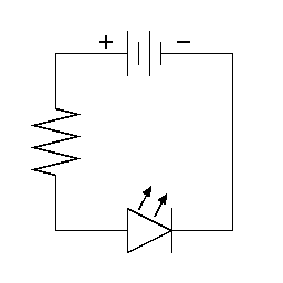
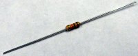
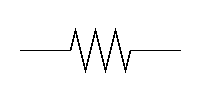
A resistor is an electronic component that inhibits the flow of electricity, typically producing heat as a byproduct. Electric heaters, stoves, and ovens work on this principle. Like diodes, resistors have two electrodes typically connected to a cylindrical housing. Unlike diodes, resistors are not directional, so they can be wired in either direction. The amount of resistance is measured in Ohms (denoted with a capital omega). See the diagrams on the right to see an example pictures of a resistor and how a typical resistor is represented in electronic circuits. At the far left portion of your breadboard, build the circuit shown in the diagram on the right. When the battery is connected, the LED should glow very faintly (you may need to shield the ambient room light or dim the room lights to see the faint glow of the LED. The reason the glow from the LED is now much fainter is because the resistor has reduced the amount of voltage difference across the electrodes of the LED, thereby reducing the current flowing through the LED.
Circuit Design and LayoutIt will help you build these cicuits if you keep them as compact horizonally as possible. This means use a few columns as possible and use the shortest jumper wires you can to connect components. Laying the jumper wires for a circuit flat to the board will help you identify individual circuits. As you build complex circuits out of smaller modular components, connect these with longer jumper wires that loop rather than lay flat to help distinguish them from the intenal circuitry of the subcircuits. Transistors
A transistor is an electronic component that uses a semiconductor to either enable or inhibits the flow of electricity, based on the voltage of a third input signal. As we saw in the video Transistorized, the first transistor was a point-contact transistor made from germanium and gold contacts. Today, transistors are most commonly made from silicon. We are using Field Effect Transistors (FETs) with an N-channel, in which a positive voltage on the gate electrode will pull electrons near it, allowing current to flow between the source and drain regions, as described in the videos we watched. See the figure above to see an example picture of a transistor and how a typical transistor is represented in electronic circuits.
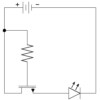
Build the circuit in the above left figure to allow the current from the resistor to connect to the gate of the transistor. This small signal is amplified in the transistor, effectively allowing current to pass to the LED and turning it on. If you connect the gate to the negative bus, the LED will turn off. The behavior of the LED is unpredictable when the gate is not connected. When you have a working circuit, feel free to repeat Walter Brattain's famous exclamation "This thing's got gain!" 
It is imortant to always use a resistor in the circuit on either the source or drain electrodes to limit the flow of electricity flowing through the transistor. Note that the simple LED circuit does contain a resistor because it is built into the LED we are using for this project. If too much current flows through the transistor, there is a chance you will permanently damage it and it will fail to function correctly. This may be accomapanied with heat, smoke, or fire. Should you be concerned if a transistor is bad, you can always swap it into this simple LED circuit to test it. In the subsequent experiments, you will take the output of the new circuits you create and connect them to the gate in this circuit to amplify the output signal. You may want to attach a small jumper wire to an bank of holes adjacent to the location of the components on the breadboard to facilitate making future connections. You can also use this circuit to test a transistor to see if it is functioning correctly. This may be useful if your transistors get hot enough to smoke or if you want to rule out a bad transistor when testing a circuit. Modularity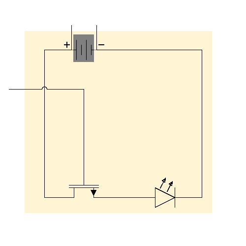 As you build circuits, there is a lot to connect (physically and mentally)!
One conceptual tool you can use is modularity. Rather than looking a
large diagram with lots of very small components, think about groups of
components having specific functions. For example, the circuit you just built
can be thought of having power inputs (+ and -) and one signal input.
This is shown in the figure on the right, where the yellow box contains the
LED circuitry. In this case the circuit has only two components
and therefore is very simple.
However, thinking about this circuit in this manner will allow
you to focus on the connections that allow it to interface with other
modular entities.
As you build circuits, there is a lot to connect (physically and mentally)!
One conceptual tool you can use is modularity. Rather than looking a
large diagram with lots of very small components, think about groups of
components having specific functions. For example, the circuit you just built
can be thought of having power inputs (+ and -) and one signal input.
This is shown in the figure on the right, where the yellow box contains the
LED circuitry. In this case the circuit has only two components
and therefore is very simple.
However, thinking about this circuit in this manner will allow
you to focus on the connections that allow it to interface with other
modular entities.
This modularity is an example of a powerful mental tool called abstraction. Computer scientists use abstraction all the time to help manage complexity. Modern integrated circuits have nearly a billion transistors in one big circuit. Understanding the complexity of such a circuit would be impossible without abstraction. Representation of Boolean Logic Values using ElectricityWe conceptually think of information on computers represented by a pattern of binary digits or simply bits A binary object has two states, most commonly 0 and 1, but often seen as True and False, or High voltage and Low voltage. In our experiments we will represent a high voltage as a 1 and a low voltage as a 0. Logically, we will think of a high voltage representing a 1 and a low voltage representing a 0. Electronic circuits can be used to implement functions that combine variables using Boolean logical operators (NOT, AND, OR, NOR, NAND, and XOR). These operations are Named for the mathematician George Boole, who published An Investigation of the Laws of Thought in 1853. These operations form the basis of all electronic processing on modern computers as we will see during this course. Logical NOT gates
Construct a NOT gate based on the circuit diagram shown on right. Test your circuit by connecting the output to the input of the simple amplification circuit from the previous step. Use a jumper wire to control the input to the circuit by alternatively connecting it to either the positive or negative bus. You should see the LED light up (0) when the negative (1) input is selected and the LED should be off (0) when the positive (1) input is selected. When no input is connected, the output is unpredictable. 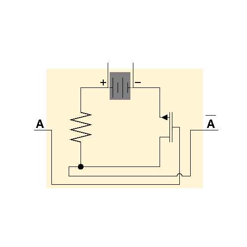
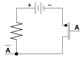
As before, you can think about the NOT circuit in a modular manner as you did with the LED circuit. It has two power inputs (+ and -), one signal input (A) and one signal output (A). This conceptual box is shown on the right. Note the input and output sides are reversed, but the internal organization remains identical to the NOT circuit described above. This modular conceptual model will help you construct more complicated circuits. Logical NAND and AND Gates
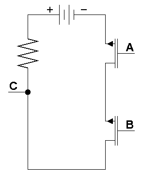
The NAND gate is logically equivalent to a logical AND followed by a NOT. Construct aNAND gate based on the circuit diagram shown on right. As before, connect the output of the NAND gate to the input of your amplification circuit (disconnect the NOT input). To test your circuit, you will need to jumper wires to connect to the positive and negative bus lines. There are four possibilities to test because there are two inputs with two possible values for each input. When no input is connected, the output is unpredictable. 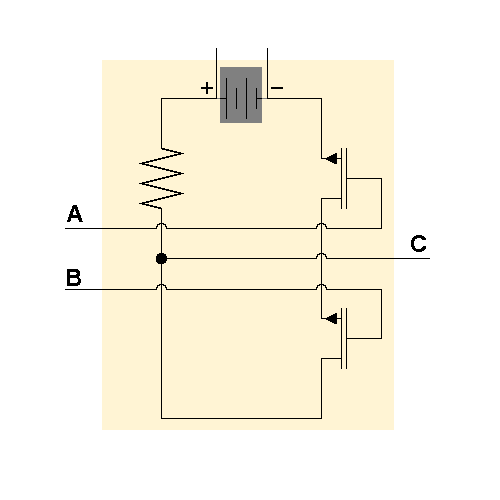
As before, you can think about the NAND circuit in a modular manner as you did with the LED and NOT circuits. It has two power inputs (+ and -), two signal inputs (A and B) and one signal output (C). This conceptual box is shown on the right. Note the input and output sides are reversed, but the internal organization remains identical to the NAND circuit described above. Note this modular circuit is very similar to the logical gate schematic for the NAND gate shown above. Thinking of this circuit in this manner will help you construct an AND gate.
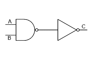
Use the NOT and NAND gates together to construct a working AND gate by simply connecting the output of the NAND gate to the input of the NOT gate. Test this circuit as you did the NAND gate. This type of circuit where two or more logic gates are used in a circuit is called a combinational logic circuit. This semester we will see how elaborate combinational circuits are used in modern computers to perform nearly every function of the CPU. Logical NOR and OR Gates
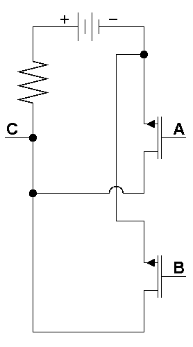
As you did for the NAND gate, construct a NOR gate based on the circuit diagram shown above. The NOR gate is logically equivalent to a logical OR followed by a NOT. Test this circuit as you did the NAND gate.
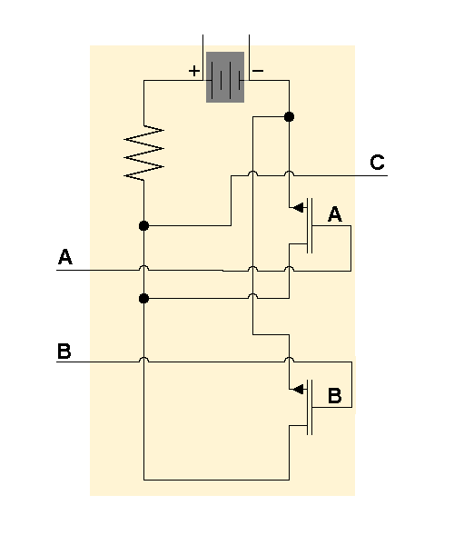
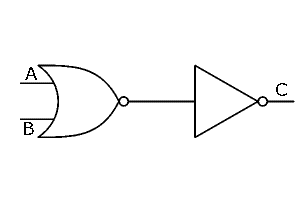
As before, you can think about the NOR circuit in a modular manner as you did with the LED, NOT, and NAND circuits. It has two power inputs (+ and -), two signal inputs (A and B) and one signal output (C). This conceptual box is shown on the right. Note the input and output sides are reversed, but the internal organization remains identical to the NOR circuit described above. Note this modular circuit is very similar to the logical gate schematic for the NOR gate shown above. Thinking of this circuit in this manner will help you construct an OR gate. As you did in creating an AND gate, use your NOT and NOR gates together to construct a working OR gate. Test this circuit as you did the other gates. Exclusive OR (XOR) Gates
Show the XOR operations (A XOR B) is logically equivalent to ((A OR B) AND (NOT (A AND B))) by completing the corresponding truth table below.
Recall the two laws of DeMorgan:
Create a logical expression that is equivalent to an XOR operation using only NOT, NAND, and NOR operations and prove its correctness using a truth table. Draw the schematic diagram of a circuit that performs an XOR operation using only NOT, NAND, and NOR gates using your logical expression from above. Construct an XOR circuit based on your schematic from above. DeliverablesYou must show me the correctly working circuits you have assembled. See the grading rubric.
Further Explorations for Fun
References
Copyright © 2019, David A. Reimann. All rights reserved. |